A rotating shaft inside industrial machinery carries two fundamental load types. Radial forces press perpendicular to the shaft, like a heavy belt pulling downward. Axial forces push along the shaft's length, similar to a propeller thrusting against its mount. The Cylindrical Roller Bearing handles the first category with exceptional efficiency. Its line contact between rollers and raceways distributes radial pressure across a wide surface. This design delivers high stiffness under heavy radial loads while maintaining reasonable friction levels. But what happens when axial forces enter the system? Does this bearing type simply absorb those loads too, or does proper design require a separate thrust bearing? Bearing-Manufacturer, a specialist serving mining, construction, and conveyor industries, answers this question weekly for engineers worldwide. The short response involves geometry, contact angles, and flange design. The complete explanation requires examining how this bearing's internal construction limits its axial appetite.
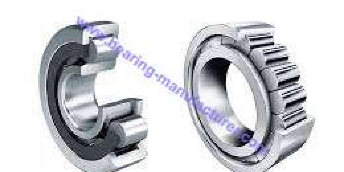
A standard bearing of this type features rollers positioned parallel to the shaft axis. These cylindrical elements ride between two raceways, one on the inner ring and one on the outer ring. Under pure radial load, each roller maintains full-length contact with both raceways. This configuration provides excellent radial rigidity. However, applying an axial force changes the picture dramatically. The rollers, being straight cylinders, have no natural mechanism to accommodate sideward push. An axial load tries to slide the rollers sideways along the raceway width. The roller ends contact the ring flanges at small points. This concentrated contact creates high surface pressure and elevated temperatures. Operating time under significant axial load remains short before wear or seizure occurs.
Some variants of this bearing include flanges on one or both rings. A single-flange design allows limited axial guidance in one direction only. The flange provides a thrust surface for the roller ends when axial force pushes in that specific orientation. Reverse direction receives no support. Double-flanged designs on both rings permit restricted axial displacement in both directions but still offer minimal load capacity compared to radial capability. Application guidelines generally recommend axial loads not exceed a small fraction of the bearing's radial rating, often ten percent or less. Exceeding this threshold requires complementary thrust bearings regardless of flange configuration. A designer cannot treat this bearing type as a bidirectional axial component even with complete flanging.
The mechanical explanation involves roller end geometry. These bearings use either flat or spherical roller ends. Flat ends contact flanges along a rectangular surface. This geometry works for occasional axial positioning but generates sliding friction during rotation. Spherical ends point-contact flanges, reducing friction but also reducing contact area. Neither configuration supports sustained axial loads efficiently. Heat generation accelerates dramatically under continuous thrust. Lubricant film breaks down at the flange contact zone. Metal-to-metal contact follows rapidly. In contrast, a dedicated thrust bearing uses tapered or angled rolling elements designed specifically for axial force transmission. Those components maintain proper lubrication films under thrust because their geometry creates favorable oil wedge conditions. This bearing family lacks that hydrodynamic feature on its flange faces.
Application examples illustrate the principle clearly. A conveyor belt roller experiences pure radial load from belt tension and material weight. No significant axial force occurs. A standard bearing of this type suffices completely. A gearbox input shaft with helical gears produces both radial and axial loads. The gear's helix angle pushes the shaft along its length. Here, this bearing manages the radial component, but a separate angular contact ball bearing or tapered roller bearing handles the axial thrust. A printing press cylinder with slight misalignment needs axial float capability without heavy thrust. A bearing with flanges on the outer ring allows the shaft to slide axially while supporting radial load. This application uses the bearing's axial clearance function, not its load capacity.
Combined loading arrangements appear frequently in industry. A common configuration pairs one such bearing with two angular contact bearings. The first supports the heavy radial load while allowing thermal expansion movement. The angular contact bearings, mounted back-to-back, control axial position in both directions. Another arrangement uses this bearing type alongside a separate thrust bearing mounted on the same shaft. The thrust bearing absorbs all axial force, leaving the other free to focus on radial support. This separation of duties extends system life because each bearing operates within its optimal load direction. A single bearing type attempting both functions would compromise either radial stiffness or axial durability.
Manufacturing quality influences how much incidental axial load this bearing can tolerate. Premium manufacturers like Yiwu DeLian Bearing Co., Ltd. control flange surface finish, roller end geometry, and internal clearance precisely. Their ISO-certified production lines employ CNC grinding machines achieving consistent flange angles and smooth finishes. Superior surface quality reduces friction when roller ends contact flanges under axial load. Better material selection and heat treatment increase resistance to surface fatigue at contact points. A bearing from a quality factory handles occasional axial misalignment or light thrust better than an economy alternative. However, even the finest product cannot replace a purpose-designed thrust bearing for continuous axial loading. The physics of rolling element contact sets absolute limits regardless of manufacturing precision.
Cost considerations affect bearing selection decisions. A single bearing that attempts both radial and axial jobs often requires oversized selection, raising purchase price and creating friction losses. Two separate bearings, each optimized for one load direction, frequently cost less combined than one compromised solution. Operational expense also decreases because properly loaded bearings run cooler and require no premature replacement. Installation space sometimes limits the two-bearing approach, forcing designers into creative arrangements. In tight axial spaces, a designer might select a flanged version for light thrust, accepting reduced axial life for packaging reasons. This tradeoff demands careful calculation and realistic load estimation.
Returning to the original question about axial load effectiveness: this bearing handles incidental or intermittent axial forces when equipped with appropriate flanges. Continuous or heavy axial loads require complementary thrust bearings regardless of bearing quality or flange design. The roller geometry fundamentally lacks the oil wedge formation needed for sustained axial pressure. Engineers specifying bearings for gearboxes, conveyors, or printing equipment must calculate both load directions separately. Ignoring axial components leads to premature bearing failure, unexpected downtime, and expensive repairs. Selecting the correct bearing arrangement means matching each load direction to a bearing type designed for that specific force direction. https://www.bearing-manufacturer.com/product/ presents a full range of Cylindrical Roller Bearing options alongside angular contact, tapered roller, and thrust bearing choices for complete system design. Their engineering team assists with load calculations and arrangement drawings. For any rotating machinery designer facing combined loads, the correct approach separates forces rather than combining them in a single bearing type. Given that geometry prevents efficient axial transmission in cylindrical designs, does your current application risk premature failure by asking one bearing to do two jobs?